70's Johnson 9.5, separating lower case problems

TinBoats.net

Help Support TinBoats.net:

This site may earn a commission from merchant affiliate links, including eBay, Amazon, and others.

oakback

Member
Joined
Oct 30, 2013
Messages
13
Reaction score
0
Location
Tallahassee, FL
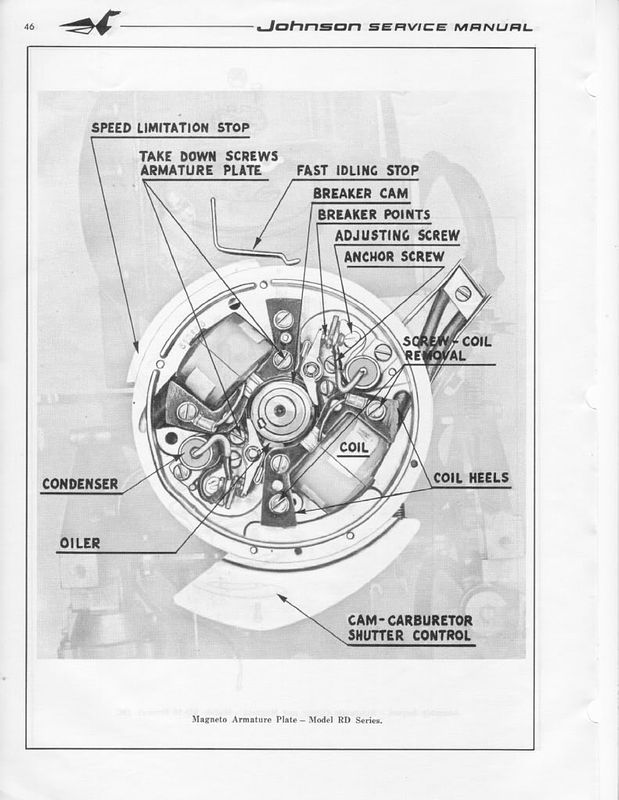
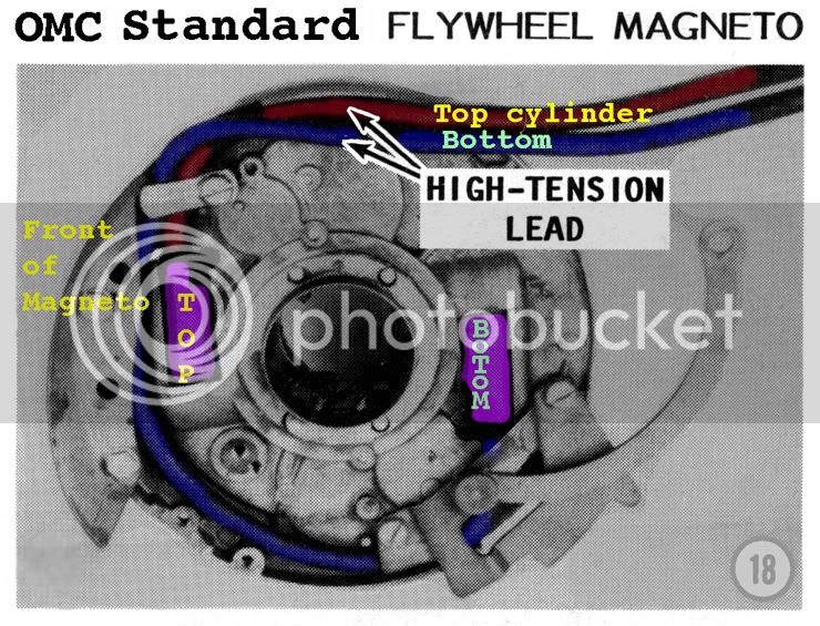
I removed the foot and the water pipe came with it, and I've failed at trying to stab it back into where it belongs. So I'm attempting to split the lower case, remove the power head, remove the exhaust manifold, and put the pipe back where it belongs.

I've got the lower case nearly apart, but there are 3 bolts at the top/center/front/inside that are really hard to reach. I managed to get a socket on one and remove it, but the other 2 are impossible to get a socket or wrench on. Any tips are appreciated.

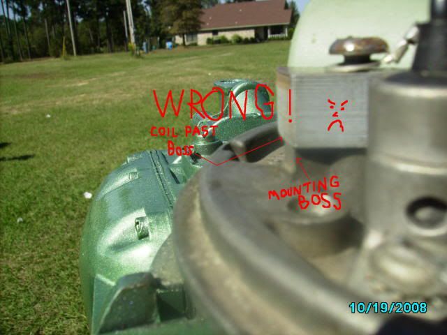
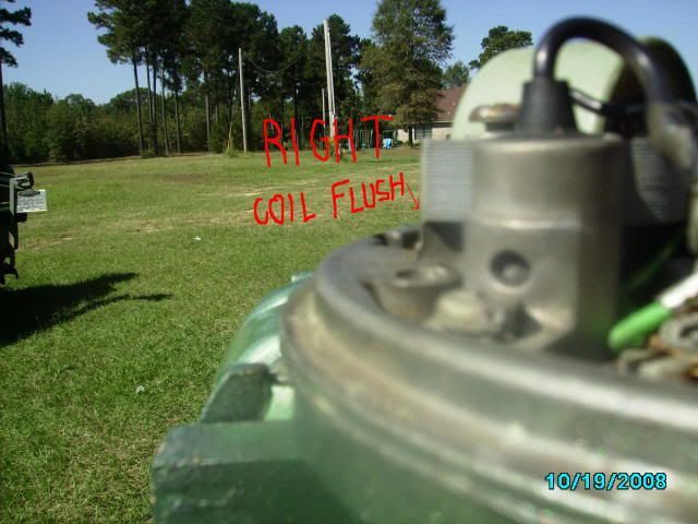
Also if there are any "while I'm here might as well..." things I should do, let me know.
 
Bummer. :(

I know there are some gents on here that are very knowledgeable about Johnson's. I'm sure they will be along to help you. They will know exactly what to do and how to tell you to do it. :) Maybe Pappy will stop by.

Best of Luck. I'll be watching, hoping to learn more myself.
 
I'll get some pics tonight. In the mean time, I'll see if this can help. It's a pic I found online, but the red oval is about where there are 3 bolts holding the left and right shell together. The heads of the bolts face to the right (when looking from the rear). The shift linkage blocks access from the right, and the flywheel blocks it from above. I can get a wrench to it, but there's no room to turn with the wrench.

And I'm also asking if there's anything else I should address since I'll have the powerhead out and the exhaust manifold off (eventually).
 

Attachments

  • Untitled.jpg
    Untitled.jpg
    48.1 KB · Views: 1,101
Funny - I took that pic. It's my motor (66 9.5). :mrgreen:

Not sure if I can help on the first issue you are having. Once apart, replace the main seal between the Power Head and exhaust housing.

Good luck. I'll be watching this thread so I can see how you did things.

CMOS
 
Here ya go, the screwdriver is on it. There's another one immediately forward of that one.
 

Attachments

  • IMG_20150825_190720645.jpg
    IMG_20150825_190720645.jpg
    28.8 KB · Views: 1,082
Yes, you must removed the fly wheel to get to those bolt heads. Please take pictures with a digital camera as you go. Use zip lock bags to separate the different areas of the motors. Some of the those parts are tiny and can easily be lost. If you have not done that I would do that now, so you don't loose anything.

Here is a you tube video that will give you a good idea how to remove the flywheel safely. Do not use a gear puller are you may damage/warp the flywheel.

https://www.youtube.com/watch?v=Nz1st4XnsX4
 
cajuncook1 said:
Yes, you must removed the fly wheel to get to those bolt heads. Please take pictures with a digital camera as you go. Use zip lock bags to separate the different areas of the motors. Some of the those parts are tiny and can easily be lost. If you have not done that I would do that now, so you don't loose anything.

Here is a you tube video that will give you a good idea how to remove the flywheel safely. Do not use a gear puller are you may damage/warp the flywheel.

https://www.youtube.com/watch?v=Nz1st4XnsX4
That's great, thanks. I've already got things organized in ziplock bags, no way I'm ever going to rely on my memory.
 
I got the case apart, turns out those bolts do not need to come out. There was one more large bolt I missed. So I suppose I didn't need to remove the flywheel, but it gave me a lot more room to see what was going on.

I managed to only break one bolt, and that was one of the two main motor mounts (the large acorn nut you see on either side). It looks easy to replace.

Getting it all back together will be interesting. I found a random spring washer kicking around in there, no idea where it came from. Also a rubber bumper sort of thing fell out before I could see where it came from. But it shouldn't be too bad.

LFGASiYKYjYhijFTFOzzRA9OYZn6RE2cw5ei2sgYoQQ=w507-h899-no
 
Removing the flywheel makes things a heck of a lot easier to remove and put back to together, so it was good that you did. Also, when you to wrap things up, it is off to clean, inspect, and service your ignition.

While you have the case halves apart, you need to evaluate a couple of things. These things involve certain parts on the motor that can cause exhaust leaks that will make your motor run poorly with the hood on. The Evinrude and Johnson 1964 to 1973 9.5hp outboard are known to suffer exhaust leak issues that have drove some owners and mechanics crazy if they did not know what they were looking for. The exhaust escapes up into the hood and smothers the motor. So they run poorly or erratically. The motor need fresh air too.

There four known potential exhaust leak areas.


1 = Exhaust housing seal. (can be dry rotted, torn, deformed and misshaped). This allow exhaust gases to flow up.

2 = Exhaust hose (can be dry rotted, torn or not well secured.) With the engine running you can pour a little soapy water and it will bubble from the pin holes or unseen tares.

3 = Shift rod boot. (This is often over looked because of its location) If it is torn, or missing it will cause an exhaust leak issue.

4 = The impeller housing seal and the washer. (They are often missing because people forget to put them back or lost)


These four area listed help keep exhaust gases out of the enclosed hood area.


The shift rod is NLA (no longer available, but there is someone who makes this piece.( You have to scroll all the way down the link.

This is the home link, but one list below is to the shift rod boot.

https://www.nymarine.ca/

https://www.nymarine.ca/grommets.htm

309631 shift rod boot

309830 Exhaust boot


Thanks, that's helpful. Luckily the shift rod boot looks great, but I broke the head off one of the bolts that secures that plate in place. I need to get the corroded shaft out, hopefully without damaging the threads around it.


Im going to post some extra information for your reference and help you along with this motor.


Here is a diagram of a generic OMC (Johnson/Evinrudle/Gale) ignition assembly. You will have to remove the coil designated for the top cylinder and put the oil wicker in. It should be already be coated with a very light oil. (not grease). The purpose of the oil wicker is to lightly lubricate the outside riding surface of the cam so the point shoes do not prematurely wear. If you look at the points they have little shoes that ride along the cam.

Ignitionplateandoilwick.jpg


FYI: You can only set(gap) one set of points at a time. Put the flywheel nut back on(turn with a wrench or ratchet clockwise) to allow you turn the crankshaft. (Please remove both spark plugs to make it easier to turn the crankshaft and prevent accidental starting)

You gap the point to 0.020 when the point shoes is at the top(high point of the cam). It should have a mark along with the word top. Then you will turn clockwise to the next set of point 180 degrees and set those points the same way. You will notice that the point of the previous set will be closed and when you come around again they will open up. *** When they are open no current is allow through. This is how you set your timing with the points.***

When you go to set the point's gap. Very gently snug the anchor screw, then adjust the gap with adjusting screw and the feeler gauge until the feeler gauge is sliding through with slight resistance only. Then tighten the anchor screw. Repeat procedure with second set of points. Please make sure your hands are clean and the feeler gauge is clean, because oil on the points can foul them up and create resistance....poor or no no spark. ALways use a spark check to evaluate spark. It should jump minimum 1/4 inch. Blue sharp snappy spark.

Here is a picture of a spark check...Cheap $6

sparktesterpic.jpg


Here is a picture of how to tell which wire is going to the correct cylinder.


TopCyl.jpg


If your using the existing wires then cut about 1/4 inch of end going the coil, so you have clean un-oxidized copper contacting the spiking in the coil. Twist the end of the spark plug wire onto the coil spike. If you have replaced the wires, make sure they are 7mm copper metal core and not the automobile stuff.

***** Please make sure two things*****

1.) Make sure all the wires are tucked away under the flywheel and not rubbing up against the cam or crank, because with will eventually get damage and create a short, then no spark!! Be sure to reconnect the stop wires back on correctly.

2.) Make sure the coil heels (ends) are evenly lined up with the mounting boss.

Here are some pictures. (Compliments of JBJennings..nice fella)

wrongcoilmount.jpg


rightwaytomountcoil.jpg


Lining up the coil heel with the mounting boss prevent damage of the coils and the flywheel magnet, prevent rubbing as the flywheel turns.


I hope this helps ya out! Might have gone overboard a bit but wanted to make sure you had a good idea.


Go to Auto Zone or similar store, they loan out a compression gauge with a deposit. Check your compression on your top and bottom cylinder. Just wanting you make sure you do not have compression issues. You can wrap a pull rope around the flywheel and manual pull until you get your spring starter repaired.

Here is a link to show how to do a compression test.
***Please let me know what the compression value is*** You may have to pull the rope 4 or 5 times to get maximum compression reading and pull on the rope like you mean to start it. Reminder, remove both spark plugs then test one cylinder at a time.

https://www.youtube.com/watch?v=PyCw4SiuT2I

Here is the part number for the carburetor kit for your motor. There is no Sierra or aftermarket kit. Only OMC kit availabel for the this motor.


Carburetor kit part number
= 382048

Here is link and parts diagram for your motor and where you can by your parts at a decent price.

https://www.marineengine.com/parts/johnson-evinrude-parts.php?year=1968&hp=9.5&model=MQ-14D

Here are some carburetor settings.


Carb Needle Adjustments For Asorted Carb Variations by Joe Reeves

these adjustment are for the older engine. 1980 and earlier, and the current small hp ob's. not for fixed jet outboards.


(Carburetor Adjustment - Single S/S Adjustable Needle Valve)
(J. Reeves)

Initial setting is: Slow speed = seat gently(turn in clockwise), then open 1-1/2 turns(turn out counter clockwise). Do not tighten or force the slow idle needle shut or it may damage the needle.

Start engine and set the rpms to where it just stays running. In segments of 1/8 turns, start to turn the S/S needle valve in (clockwise). Wait a few seconds (10 to 15 sec) for the engine to respond. As you turn the valve in(clockwise), the rpms will increase. Lower the rpms again (turn your throttle slightly slower) to where the engine will just stay running.

Eventually you'll hit the point where the engine wants to die out or it will spit back (sounds like a mild backfire). At that point, back out(turn out counter clockwise) the valve 1/4 turn. Within that 1/4 turn, you'll find the smoothest slow speed setting.

When you have finished the above adjustment, you will have no reason to move them again unless the carburetor fouls/gums up from sitting, in which case you would be required to remove, clean, and rebuild the carburetor anyway.
 
Please save the procedure photos to your pc for better viewing and safe keeping
 

Latest posts

Top