Jet Jon Build Pics ...VIDEOS LINKED!!!!!!

TinBoats.net

Help Support TinBoats.net:

This site may earn a commission from merchant affiliate links, including eBay, Amazon, and others.
majkowskid said:
do you not think it could be from the ribs on the bottom of the boat that are in this pic?
or is my spoon area not right?
ribs.jpg

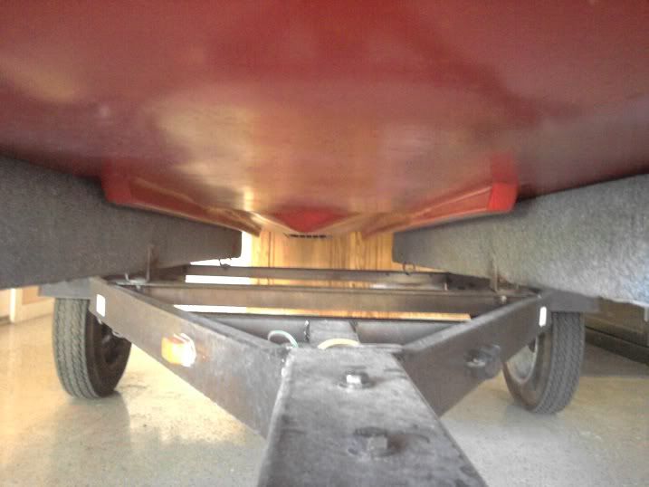
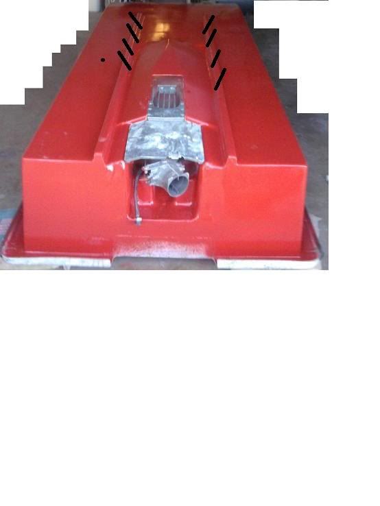
No, but looking at the pictures, it appears that you have a 'step' between the hull and the body of the pump intake, it appears the pump intake is not flush with the hull, like it may be inset by a half inch or so. (Correct me if I'm wrong, and if I'm wrong, then, ignore the next part)

This step could be part of your problem, it will cause turbulence, right before the intake, which is something you do not want to do.

You could try to fill this void somehow, and try to blend and taper it, but the pump is still going to be inset from the hull, so, I don't think that will eliminate the problem.

Hate to say it, but it looks like the best option is to try to drop the pump a little bit, to get it flush with the bottom of the hull. Unfortunately, this may also mean having to change your motor mount design, to also drop the engine lower, to keep in line with the pump when you lower it. I know that isn't what you want to hear, but IMHO, I think that's the best course of action.


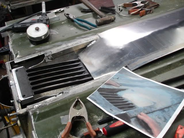
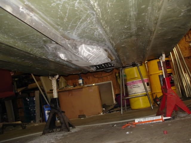
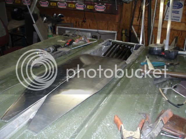
this is what i was trying to explain about cutting some slits in the ribs to direct water to the pump... also thought maybe one of the higher end intake grates with the scoop on it may help keep the pump loaded?
boat2-1.jpg
[/quote]


A top loader grate. Instead of having numerous longitudinal tines, most top loaders have 2 scoops on them, and they are supported by one massive tine on either side.

I ran a top loader on the Aluma-Jet for a while, but the problem with it, is when you operate in areas where there are weeds, etc. As it doesn't have a 'grate' so to speak, it becomes an even bigger vacuum cleaner, sucking up everything in its path.

When I designed the weedless grate on my boat, I really wanted to keep the top loader grate, but it was logistically and mechanically impossible to have a top loader grate AND a conventional grate with longitudinal tines operated by a push pull cable on a pivot..... so I had to choose between being able to operate in heavier chop without cavitation and not having a way to clear a fouled intake grate, or being able to clear my grate, but being more limited to operating at slower speeds in chop. In the end, I went with my weedless grate.

One other thought I had was that the sharp "V" in the hull ahead of the intake COULD be causing some turbulence, but before you try to modify that part of the hull, I would suspect that step between the pump and the hull.
 
Bills build was the one I was thinking of when I mentioned the plywood built up. The step that PSG mentioned is where better pictures could save the day.

I'm in the same boat with the grate, I like being able to glide over the weed beds but have to go slower in chop vs. sucking up everything in the water. I'm sure I'll be sucking up leaves in a week or so.

Jamie
 
Yeah, the cypress trees are starting to drop some of their foliage in the rivers and swamps around here. Even with the weedless system, when I came back from a trip to the Waccamaw River last week, I found a wad of leaves on my intake grate, and another small wad wrapped around the push-pull cable that controls the weedless grate. Even so, it didn't cavitate much, which surprised me. Heck, it surprised me that I had a wad of leaves under there, as I did activate the grate a couple of times when I was in the river.

Another thing I suggest for those who run in debris-filled water....get yourself a "Shurflo" inline water filter, with 1/2" barb fittings, and plumb it in between the pump and the engine. It has a removable cap, and a strainer screen that will prevent trash from clogging your water passages in your engine.

One other thing I would suggest, and I went ahead and put one on my boat.....get a teleflex water pressure guage (they are 2" in diameter, like most fuel, temp, voltage guages) it reads from 0-35 PSI. You will have to run a small diameter hose (very similar to speedometer hose) from your console back to the engine compartment.

Plumb the T fitting in AFTER the water filter, not before. If you put it inline before the filter, if the filter becomes clogged, the guage will still read water pressure. If you put it after the filter, then, if the filter clogs, it will show a drop in water PSI readings, and you IMMEDIATELY know that there is a problem, you're not having to constantly watch indicator stream fittings to see if they're peeing, etc. Simply glance at the guage, and it will tell you in an instant.
 
thanks for the help guys! i've got a couple things i want to try, but it may have to wait a little while. i think first thing will be an intake grate. always a good upgrade anyways.

as far as the "step" you speak of, are you referring to the left and right sides of the intake grate as shown in the pic above?? (btw, i'll have pics this weekend sometime... my camera wouldn't work yesterday so i'll have to borrow one)

if that's what you're referring to, i may be able to alleviate that this winter... i can potentially fill that void and fiberglass over it, but it's gonna be a pain in the rear now that i can't flip the boat!
 
Ranchero / PSG. I found a little better picture of the bottom... still dont have a camera yet. this was before it was painted.

IMG_20110607_052155.jpg

the circled areas are what i think are causing the problem now. i did a bit of research on the purpose of a spoon on a jet boat, and now i understand what you're talking about.

here's my idea /thinking:

i can taper the large circled area (which sticks down quite a bit from the flat portion of the boat) by creating a template out of carving foam, and tapering it towards the front of the boat 2-3 feet. i can fiberglass this on to the bottom of the boat.
the two smaller circled areas are little "pockets". i rushed this area of the fabrication, and i admit that. i know they need to be smoothed out.

do you think this would help? i would think that the natural "spoon" that is built into the jetski hull that i attached to the boat should suffice for what it needs. i'm really thinking that the large circled area is just diverting water from hitting the pump because of the turbulance caused by it.
 
Yes, that's the area I was referring to (your last photo with the circled areas) In the pics with the pump installed, that area appears to be stepped up from the pump. Also, those areas you have circled could cause turbulence, but if you have the pump flush with the bottom of the boat, it wouldn't be as severe. That step in the transition between the hull and the body of the pump, combined with the peak and valleys that you show in the circled area....would definitely be the primary suspect for cavitation. The longitudinal strakes to the outside of the pump would cause turbulence behind the strakes, as well as on the leading edge, but that is not in front of the pump intake, so it would have no effect on the pump's performance.
 
yeah, the more i think about it that's probably a lot of the problem. here's a quick drawing of what the boat technically looks like from the side view, but exaggerated a lot.
boatprofile.png


i'm thinking i can profile it down this winter and create a gradual slope under the boat, and integrate a spoon like jamie's. i think you guys are right... the ribs probably aren't affecting it as much as i think. i think that big bump is pushing the water clear of the pump.
 
For all visual purposes, the area you have shown in red indicates the location and shape of the air pocket that is forming as the boat moves across the water. This is most likely the source of the majority of your cavitation.

The area that I was initially referring to, is on the BACK end of that hump, where your pump bolts into the hull. From previous photos, it looked like there was a step in the transition between hull and pump, like the pump may be inset from flush with the hull by about 1/2" or so. If that's so, then, that step could also cause some issues with cavitation.

But after seeing the drawing you did, I would also tend to agree with your assessment about that step on the front side of the hump causing the problem. That is a pretty large step, and if it does not transition in some type of smooth taper, it will definitely create an air pocket, a large one in fact, likely enough to cause it to cavitate. It's not cavitating on flat water because the hull is flat out, and has displaced the air from underneath, and will continue to run as such until you hit some chop, which allows air to get between the hull and the water. With a flat bottom or a spoon, this isn't an issue, as the air is displaced or dissipated by the time it reaches the pump. But if you have something on the hull that breaks up the smooth transition of the water, the air is going to collect at this point, and 'bleed off" toward the pump intake, causing it to suck up the air and cavitate.
 
good to have affirmation of what i'm thinking. it's actually a bit more complicated because there's some weird angles going on from the jet ski hull portion, but i'm going to get it all rounded out. i'm sure it'll take some time espescially working on my back under the boat. i'm not about to disassemble the entire thing to do this :) block and tackel, raise it up a bit off the trailer, and do it from underneath.
 
got two videos posted! well, my buddy posted them on facebook, and i can't download them!

working on it!
 
dang it... doesn't work. i have to get my buddy to upload them to another site. gimme a little while :)

ranchero / psg, here's a quick pic looking from the FRONT of the boat, down the bottom. you can see that the intake grate is about 1 inch BELOW the actual bottom of the boat... but you can also see the terrible hump that i'm talking about.

IMG_20111013_170740.jpg
 
Oh, OK, yes, that shows it in better perspective. That helped clarify it for me.

Now I see that the pump IS flush with the hull. I guess some of the other photos were playing tricks on my eyes, there appeared to be some type of anomaly between the hull and the pump, I guess it was just a shadow.

Seeing the hull from this angle, I would say yes, definitely that sharp V is causing the issue with turbulence.

About the only way to fix that is by doing some glasswork, making it transition from the hump, down to nothing where it meets the hull forward of the pump, smoothing out the profile of that V and blending it to the hull.

If you do this, I can almost guarantee that the problem will be solved, as this stepped area definitely sits lower than the rest of the hull, keeping the pump hooked up won't be a problem, you might not even need the top loader grate after all .... with the pump being that low.

But again, that V is the most likely culprit at this point, as everything else appears to be correct.

You could experiment and find out for sure if this is the problem, perhaps forming up a small piece of plywood, and just scab it to the hull around its perimeter with a little cloth and resin, do a test run, and see if that fixes it.

If it does, you can easily snatch that 'band-aid' off the hull, and go ahead with your full modification like you mentioned earlier.

And if it doesn't, you are able to find out quickly, without having to put a lot of labor into modifying the hull, and there being the possibility of it not working (but I have confidence that it WILL work)

In either case, a quick expedient patch that covers the void to do a test run is probably your best bet at this point. When you get into trial and error like this, you want to experiment with modifications that require the LEAST amount of time, material and labor. that way, if and when a mod doesn't work, you haven't invested a lot of time into it.
 
Sorry to hear about your cavitation problems. Wish I was farther along with my project so I could offer you some real world advice. I do appreciate you documenting it so that those of us working on similar projects can hopefully learn.

Congratulations on the top speed. I'm sure it felt great to scoot along like that.
 
Looking at your last picture, i think the your spoon isn't big enough or shaped quite right. Right in front of the intake, needs to be the focal point of the spoon. It should be ramped, not flush or slightly "V-ed". This forces the water to keep the pump loaded.
Take a look at this: https://www.tinboats.net/forum/viewtopic.php?f=21&t=8385&start=105
The idea is to divert air to the sides of the intake (front of the spoon) and water to follow from the halfway point or just before that, along the curve of the spoon and up the ramp (rear of spoon). The spoon being curved side to side and front to back. Mine is kinda crude, Ranchero's being professional grade. But they work.
 

Attachments

  • IMG_0833.JPG
    IMG_0833.JPG
    900.3 KB · Views: 2,186
  • IMG_0834.JPG
    IMG_0834.JPG
    980 KB · Views: 2,186
  • IMG_0874.JPG
    IMG_0874.JPG
    1 MB · Views: 2,186
My 2 cents is still that you need your spoon deeper so it's drawing from undisturbed water. I can't see my intake from the front. You want the spoon to push the aerated water out of the way and draw from the clean water.

DSC06659.jpg


DSC06666.jpg


DSC06660.jpg


Jamie
 
thanks for all the input guys! definately know what i need to do now... basically redesign the entire bottom of the boat between the ribs :) i'll get it done, but it's going to be a while before i can get started. unless someone wants to donate a bunch of resin to me..... :)
 
On my boat, I didn't build any type of spoon.

Jet Pump Cut-Out Reinforcement.jpg

You can see the center strake of the boat in this photo, before the jet unit was installed. I ran it with this center strake for a year or so, and in conjunction with the top loader grate, there wasn't much of an issue with cavitation.

But when I went back to a conventional grate and modified it to be a pivoting weedless grate, the cavitation showed up again. So, what I did was to take my sawzall, lay the blade sideways, and cut about 3 feet of that strake off the boat, taking it down flush to the hull in that area forward of the pump. Then, to cap it off, I used a piece of 1/4" plate, cut to the necessary width and length to cover up the void, then welded it to the hull, leak tested, and sealed with paint. (I don't have a pic of it right now, I'll try to remember to take one today)

My boat runs pretty good without the spoon, perhaps it would have better hook-up in choppy water if I HAD built a spoon in the hull, I'm not sure.

One option we discussed doing on the next build is a 'dropped hull' Basically, cutting out the hull and modifying it to be dropped lower than the rest of the hull by about 2 inches, setting the engine and pump as low as possible. From the transom end, the drop hull would appear to be a 'V' with the point flattened out...about as wide as the pump/engine area, then tapering down to nothing toward the forward end.

We figure setting the pump lower than the rest of the hull ought to allow for running in the snottiest conditions possible, with no cavitation.
 
hmmm....

that's really weird psg... so basically you have a similar hump in front of your intake, and didn't have the issues. only difference is your intake grate.

i really think i'm going to try that first... just get a top loader grate. i'd rather try a bolt on accessory before i go and start glassing. i figure it's a good upgrade to the boat anyways.
 

Latest posts

Top