Why not use a common ground?

TinBoats.net

Help Support TinBoats.net:

This site may earn a commission from merchant affiliate links, including eBay, Amazon, and others.

CaveEagle225

Member
Joined
Feb 17, 2020
Messages
11
Reaction score
0
I’m new to wiring boats, but have done a fair amount of automotive wiring to include a complete re wire of my 67 mustang.

Why does it seem like nobody wires their boats using a common ground for multiple circuits?

I recently moved my 12v battery up to the front of my 16’ express using 6g welding wire. I used to insulated post terminals in the rear engine area to have a clean place for the engine to connect. My next step is to wire in a bilge pump and lights.

Now that I have a 6g ground wire running the length of the boat, it seems like I should be able to ground each circuit to either end of that cable to minimize wiring. Ans then then I only need to run the positive lead to switched & fused power..

What am I missing?
 
Nothing really ... it is just more how boats and loads used are laid out, at least to my thinking.

STERN - Think of it ... items in the rear can be grounded to the Neg battery post or a dedicated 'power' post off the battery (for grounds), for things like stern light and bilge pump.

In the rear of my big(er) boats I mount an Ancor Power Post as a common ground. Each battery, the OB cable, and main power harness leads all connect to this. This is a SUPERIOR method, to me, than coupling batteries together, as in an emergency I can take a battery completely out of the circuit ... even while everything is running and I have not disturbed the ground circuit at all!

MIDDLE - But then most boats use/need most power at the helm/middle of the boat, so a heavy Pos & Neg lead is brought up from the battery to power helm electronics, where most mount a fused/breaker terminal block like shown. And where most items are 'close', it just makes sense to bring them back to this block, which is acting like a common ground.

BOW - Many have nothing up front less maybe a bow light, unless you have a fancier bass fishing rig where you have another fishfinder or a repeater screen, plus trolling motor outlet.

Just make SURE that primary ground cable has enough ampacity to handle the maximum worst case load and remember for the length calculation, if 16' from the battery, for ampacity (read: wire size) calculations ... that is a 32' long circuit (for each wire, Pos or Neg), even though you only have a 16' run. Ampacity is factored on getting 12V juice there and back!

'
FuseBlock.jpg
 
Mostly because boats are often laid out with several batteries that are isolated, with each designated to certain components. One for the trolling motor, one starting motor, and sometimes another for accessories, to avoid drawing down the other two.

Most of the time accessories are wired to a switch/fuse panel and a ground bus bar, not right to the battery, and the batteries are usually close by, so it doesn't save a whole lot of wire.
 
I’ve grounded accessories to the negative trolling motor wire before to route the ground to the stern. Really the only issue I could imagine would be if you had like an extra 20+ amps on it or something. I still usually isolate my trolling motor wires but I do typically run a single larger gauge ground wire to the bow so I can bus all bow accessories altogether.
 
CaveEagle225 said:
Why does it seem like nobody wires their boats using a common ground for multiple circuits?
Depends on the layout and battery locations, but that is how I did my last boat. Rear battery handled all the electrical. 12awg wire that ran to a buss bar in the front that handled all the grounds from the bow.
 
I don't know if it's right or not but I'm doing mine as follows.
Stern battery will power controls, motor, and a bilge pump on float switch(in line fuse)
2 fwd batterys, will power trolling motor (circuit breaker) I'm then running heavy wire under console (positive to fuse block negative to bus bar) I'll run all my navigation lights, manual bilge pump (#2) livewell pump, deck lights and led headlights, and fish finders off this point. As I said I might be wrong. But if I am please make suggestions.
I'm not trying to hijack the thread, but I haven't began running wire so I'm looking fwd to suggestions lol. It seems like this will help with backfeed, or poor grounding?

Sent from my SM-T700 using Tapatalk

 
Here's a simple boat circuit, as attached:
.
Simple Boat Circuit.jpg

.
This is that 'Power Post' by Blue Sea (I mistakenly said by Ancor in an above post, but Ancor makes electrical terminations/switches) that is awesome for using as a common ground in the stern, plus it has multiple points for things like a stern light, bilge pump or other ground to be attached to.
.
P-Post.jpg

.
This is an ampacity chart to determine the correct wire size, depending if you are doing critical (bilge pumps, nav lights, horn, radio, etc.) or non-critical circuits (house lights, courtesy lights, ,etc.). Guys posted good info up above, but where most FAIL here (not those guys, :wink: mind you) is that they forget to DOUBLE the length of your longest run - per wire - for the circuit. This doubling is for ampacity calculations only.

So if you have a maximum 40 Amp worst-case load that will be 'on' at the same time and the load (item) is 10' away from the power source, then you'd need to factor for a 20' circuit, thus assuming for a 3 voltage drop as critical, you'd need to use 6 AWG.
.
Wire Ampacity Chart.jpg
 
FF6B71FF-6713-44DF-95E4-FE871F619BF1.jpeg

Why is there an extra fuse between the battery and fuse box, and no fuse or circuit breaker in the trolling motor circuit?
 
Scott F said:
Why is there an extra fuse between the battery and fuse box, and no fuse or circuit breaker in the trolling motor circuit?
Good questions; am glad you asked for clarification! The American Boat and Yacht Council (ABYC) has standards for many boat construction that various groups, e.g., USCG, marine insurance underwriters, and boat manufacturers, adhere to. Here's what they say for protecting primary circuits.

"ABYC E-11 recommends that each ungrounded conductor connected to a battery, battery charger, alternator, or other charging source, shall be provided with overcurrent protection within a distance of 7" inches of the point of connection to the DC electrical system or to the battery."

Trolling Motor Circuit - Not my DWG and I can't speak to ' ?why? ' the originator omitted that, but I can add that note, as it was originated in MS Visio. My oversight ... mea culpa, but I don't use such motors so I had to look up what companies like Minn Kota recommend - see attached PDF.

I know of instances on some ultra critical bilge pumps applications like where Owners of offshore boats prefer not to fuse them, reckoning they'd rather have the pump try to pump, even if partially clogged, vs. blowing a fuse or breaker at the worst possible time, i.e., when the boat is heeling and taking on water FAST! Admittedly that is a much debated topic ...

Fused Main Run - Protected as per the ABYC, where the fuse in that run is certainly not 'extra'. Remember that fuses or breakers serve to protect the wire run itself from burning and starting a fire onboard a boat and are not there as much to protect an installed device. For example people add an AM/FM radio and fuse the circuit thinking they're protecting the radio. Well to a point they are, but if the radio develops an internal short the fuse protects a potential over amperage from frying that wiring run.

View attachment Minn Kota Conductor Gauge & Circuit Table.pdf
 
Scott F said:
Why is there an extra fuse between the battery and fuse box, and no fuse or circuit breaker in the trolling motor circuit?

Fuse between the battery and fuse box protects the feeder to the fuse box. I have a 30A fuse that screws right onto the battery terminal and the feed to the fuse box connects to that.

My other boat has a trolling motor (and no other electronics) and that is also fused the same way.

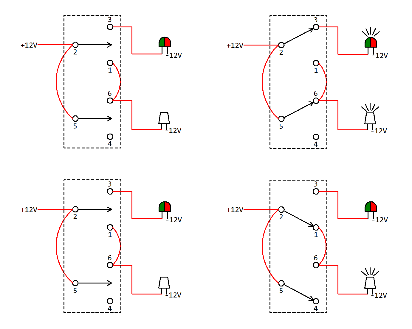
In the diagram shown, I think the nav. light and anchor light need separate switches. Nav. light with stern/anchor light when underway. Anchor light only when at anchor.

Double pole, double throw rocker switch:

nav-anchor-switch.gif
 
Galvanic Corrosion can occur if you use the hull as a common return.

Many boats use the (-) negative side of the battery as a return, not a ground. Electrically the return line is common to all branches attached to it.

Critical Systems may require dedicated wiring (+ & -), mostly for redundancy.

On a 15' boat, a common return that has the correct voltage-amperage rating for the circuit, correct size breaker/fuse, and the branch wiring is correct voltage-amperage rating for the branch, your circuit will work fine.

I would be surprised if small tin boats are required to meet any wiring standards, but check!

Boat builders handbook Electrical Systems (2003) - Boats powered with outboard engine(s) are not subject to these regulations unless there is also a gasoline powered engine installed on the boat such as a gasoline powered auxiliary generator. The outboard motor and its associated control wiring are excepted. Associated control wiring includes power cables, ignition wires, gauge wires, etc. A battery used only for the trolling motor becomes part of its associated control wiring and is therefore not subject to the regulation’s requirements, including the battery securing and restraint requirements of 183.420.

I have found a good presentation on line and attached a copy of it.View attachment Electrical-Presentation-SBCC-2016(1).pdf
 
Top